Friday, December 22, 2017

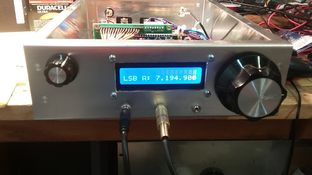
A New Look for your uBitx!

Adding a "Cool Blue" Display to your uBitx!


The standard "green background" with black lettering frequently reminds me that I suffer from Chronic seasickness -- and yes I spent four years in the US Navy. So I usually try to avoid anything that has that "seasick green" color. Today I shifted to a cool blue display with white lettering. This move may even contribute to reducing global warming.
 
Since the I2C is not being used literally any LCD can be plugged into (or as in my case connected to) the Raduino. Tell me doesn't this doesn't look really "uptown" with a real touch of class. The supplied LCD is slightly smaller and fits right in the hole. The blue one is slightly bigger in one dimensions thus I had to uses some aluminum spacers to bring it close to the front panel. Having a huge junk box helps.

73's
Pete N6QW


Tuesday, December 19, 2017

Why you need an In-Line Fuse on the uBitx Power Cord?

Protect your uBitx Transceiver!


The uBitx package as it arrives has just about everything you need to put the amazing rig on the air --sort of like right out of the box. While not recommended for long term use it can even be hooked up 'al fresco" right on the bench and you are good to go.
 
But knowing well myself and my propensity to smoke parts, I usually go the extra mile to arrange things to make them "Pete Proof". Reflecting on my earlier statement about having everything there in the package as sent from India, I did note that my Bitx40 acquired just a year ago had one additional item -- an In-Line Fuse assembly. the uBitx kit did not have that piece.
 
Being somewhat in a hurry to get my uBitx Inhaling and Exhaling RF I simply grabbed the power cord from the Bitx40 and used that for the new rig. That was a fortunate action on my part sometimes known as dumb luck.
 
So here is the why that you should have an in-line fuse on your power cord:
 
  1. The uBitx includes a diode that is soldered across the power connector so that when the power is connected properly the diode is reversed biased --no issues there. But if you reverse the leads and have the power being fed backwards the diode conducts to ground and depending on how many amps in your supply you will smoke the diode and hopefully trip power supply --but if you are using a 30 amp supply like in a home station, once the diode is crisped beyond recognition and if it opens up --you will have reverse voltage applied to your beloved uBitx. The in-line fuse using a value like 2 Amps Fast Blow will open as soon as the diode starts to conduct and your rig will be safe.
  2. But the in-line fuse has another important use which I discovered when I tried an interesting maneuver. I have what I call a 40 Meter droopy dipole out in the back yard. Actually that dipole is 98.6 feet long and by using an antenna tuner am able to run that dipole on bands like 75M, 60M and 40M. The magic number of 98.6 has to do with an extended dipole length actually 3 half wavelengths on 20 Meters where it was initially used --yes it is a gain antenna on 20M. That was used before I had the beam. So I thought I would test the uBitx on 75 M and using CW as the tune signal attempted to tune the antenna tuner on 3.805 MHz. As I started the dip and load -- the uBitx went dark. Ouch what did I do now? There was no voltage on the power connector at the back of the chassis yet there was voltage at the supply --well folks that has to be an open fuse. Sure enough the fuse was blown. So important step here! When something like this happens don't put in a new fuse and just recycle things. Take time to ask why did it happen. The issue is current draw on high SWR conditions. Since there is no foldback current protection of the IRF510's that would sense high SWR and thereby reduce the power level until the condition is corrected --you need something else! The fuse will serve that purpose. You might have to put a 2.5 Amp Fast blow in there --but no 15 amp fuses!
This is what I did.
 
 
Save your finals --yeah I know they only cost $0.69 a piece but a fuse would cost you less than that.
 
73's
Pete N6QW

Monday, December 18, 2017

Adding an External Linear Amplifier Control circuit to your uBitx

Adding some big "shoes' to the uBitx!


So OK the concept of the Bitx and uBitx is to operate QRP and with the new design of the uBitx having 10 watts is an excellent power level for making contacts. After three days of operation on 40 Meters it was clear the uBitx needed some shoes. I have the shoes so the problem is how to control the external amplifiers.
 
The hack here is not new as I did the same thing about a year ago with the Bitx40 so it is a proven design.
 
First I looked at the uBitx Schematic and see that one of the pins on the Arduino is "HIGH" and by grounding that pin this causes a series of actions to put the uBitx into transmit. So now the problem is how key an external linear amp and do it in such a way that considers how to accomplish this without interfering with the normal operation of the uBitx and to also have an isolated control of the linear such that there is essentially a firewall between the uBitx and the amp. The hack should also not involve changing the sketch and be completely reversible.
 
A word here about the uBitx wiring. For over 60 some years my microphones have been wired so that the Sleeve on the microphone plug is ground, the Tip is the PTT control and the Ring is the Audio. All of my microphones are wired that way. The uBitx instructions have the Tip and Ring interchanged. That is not a problem so long as you wire the microphone jack and the microphone plug the same way. The construction photos initially through me for a loop as the Orange and Violet Wires on my Microphone Jack were reversed [in the photos] from the way I wired it. It was at this point I decided to read the instructions and sure enough Farhan made it clear that the microphone input was on the Tip. The sketch I will be providing is based on my standard and not the way Farhan has suggested. So LOOK at that carefully.
 
So here is the solution to add the linear control and the parts required are: two 1N4148 diodes (literally any silicon signal diode will work), a 12 VDC Reed Relay, some perforated board, two aluminum pillars, four 4-40 screws, two 2 Pin headers, 2 one inch pieces of heat shrink tubing and two lengths of insulated wire about 14 inches long. Finally you will need an RCA Jack installed on the back panel.
 
The two diodes are connected cathode to cathode and that common connection connects to the TIP connection on the microphone. One of diodes is connected to the Orange wire (anode end) that goes to the Raduino board. The other diode (anode end) connects to one end of the coil on the reed relay. Use heat shrink tubing so that after soldering the wires to the two anodes, the heat shrink tubing is slipped over the diodes and the wired connections --No shorts here.  The +12 VDC end of the Reed relay is connected to the 12 Volt rail at the power switch in common with the red and brown wires that go to the mainboard.
 
Essentially when the PTT is engaged both diode cathodes are grounded. On the Raduino side the PIN that was HIGH is now LOW and the uBitx is placed in Transmit. On the amp control side the Reed Relay  field coil is energized and the contact closes (short to ground) which is brought out to an RCA jack on the back panel. The two diodes prevent any voltages from being back fed into either circuit and effectively isolates the circuitry.
 
My uBitx now has some "big shoes". With this arrangement I can run a small solid state amp at 100 Watts or add in a Heathkit SB200 on top of that for 600 Watts to the antenna. I no longer get reports on 40 Meters "you sound really good only not much signal". Now I can use the uBitx to Run with the Big Dogs. On 20 Meters running just the uBitx I can hit about 700 watts using my homebrew 3CPX1500A7. Life is too short for QRP! 


73's
Pete N6QW

Saturday, October 28, 2017

Raduino as NBFM TX


Here is a neat, 30 minute hack for your Raduino to turn the Si5351 into a pretty stable, solid NBFM transmitter. The hack is to add a varactor diode in series with the reference crystal oscillator and drive it with audio. I used a very simple audio amplifier to boost up the audio. Here is the circuit:

Attach a small piece of wire to clock 2 to radiate the signal. Here is the sketch :

/**
 * This source file is under General Public License version 3.
 */
#include <Wire.h>
#include <si5351.h>
Si5351 si5351;

void setup()
{
  int32_t cal=0;
  
  si5351.init(SI5351_CRYSTAL_LOAD_8PF,25000000l, cal);
  si5351.set_correction(cal);  
  si5351.set_pll(SI5351_PLL_FIXED, SI5351_PLLA);
  si5351.set_pll(SI5351_PLL_FIXED, SI5351_PLLB);

  //si5351.drive_strength(SI5351_CLK2, SI5351_DRIVE_2MA);
  si5351.output_enable(SI5351_CLK0, 0);
  si5351.output_enable(SI5351_CLK1, 0);
  si5351.output_enable(SI5351_CLK2, 1);

  si5351.set_freq(14500000000l,  SI5351_CLK2);   
  
  delay(10);
}

void loop(){

}

Thursday, August 31, 2017

Ergonomic BITX Enclosure -- 3D Print


Wow, Michael's amazingly cool BITX enclosure looks like you could use it to ask Scottie to beam you up. 
Put an end to those freakish contortions -- 3D print yourself an Ergonomic BITX box! Very FB Michael. Thanks. 

Hi Bill and Pete:

I thought you’d be interested to see my ergonomic enclosure for the BITX40. While operating homebrewed regen radios, I noticed that my hands/arms/shoulders were becoming uncomfortable after a while. After thinking about this for a few days, I realized that the dials on the front of these small radios were forcing my hands into freakish contortions—and having both hands on the dials at all times while tuning made matters worster faster! So I did some homework and determined that our arms and hands most naturally hold things toward each other, as though they are holding a small cylinder by the ends. But the conventional “dials-and-speaker-facing-front” radio case forces us to twist our hands up and outwards from our bodies to twist things. See my blog post http://blog.generaleccentric.net/?p=2009 for illustrations of this problem.

My enclosure design for the BITX40 re-orients the volume and tuning knobs toward the sides of the radio, making their operation much more natural—and pleasant. Although it’s not retro, it does have an unconventional appearance and should fit in quite naturally with all the other homebrewed solutions featured on SolderSmoke. 

You can visit my post at http://blog.generaleccentric.net/?p=2082; the box is available for download and printing at Thingiverse: https://www.thingiverse.com/thing:2508147

By the way, I also have a 3D printable mic for the BITX40: https://www.thingiverse.com/thing:2500483

73, Michael VE1LEB

Saturday, August 26, 2017

Speech Processor and Antenna Tuner/SWR meter for BITX


Check out the blog of homebrew wizard K.P.S. Kang.   OM has a nice speech processor based on the LM386.   He also has a very simple antenna tuner and SWR bridge.  FB OM.  

http://smallwonderqrp.blogspot.com/2017/08/two-essential-add-ons-for-bitx-and.html

Monday, July 24, 2017

KC8WBK's Cakepan BITX Enclosure and PVC Mic/PTT Grip


I talked to Paul KC8WBK last night during the regular 7277 kHz Sunday night BITX gathering (7 pm local). I like his BITX enclosure.  Very practical and economical.  It provides ready access to the circuitry.  He also has nice enclosure for the microphone and push-to-talk switch. He has more info on his QRZ.com page.